4 Bit Ripple Counter Using D Flip Flop
Who are the experts. I am implementing a 4 bit counter using a D flip flop.

1 A 4 Bit Ripple Counter Circuit The Output Of One Flip Flop Clocks Download Scientific Diagram
How would I design a 4-bit ripple DOWN counter using four D flip flops and no other components.
. 4-bit Ripple Carry Counter. The problem I am facing is that only first instance of T_flipflop T0 is working while other bits are on. This 4-bit digital counter is a sequential circuit that uses JK flipflops AND gates and a digital clock.
The number of output states of counter is called Modulus or MOD of the counter. Ok so as the title says im wanting to build a 4-bit ripple down counter on logisim so that I can find what 15 in binary is along with what 9 in binary is to make a mod-10 ripple down counter. 4-bit ripple counter using JK Flip Flop.
We review their content and use your feedback to keep the quality high. The diagram of a 4-bit binary ripple counter is shown in Fig. Mod 4 Mod 2 etc.
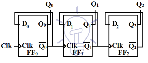
Each probe measures one bit of the output with PR1 measuring. A 4 bit asynchronous UP counter with D flip flop is shown in above diagram. The reset is the same for all the T flip flops.
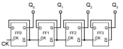
The comparison shows that the Ripple counter implemented using MOS CML D-flipflops has 2925 lesser power consumption compared to that implemented using the conventional NAND-based D-flipflops. For that I have first written the code of D flip-flop then converted it to T flip-flop and then used it to make a counter. It is capable of counting numbers from 0 to 15.
After it reaches its maximum value of 15 calculated by 24-1 it resets to zero. For the second T Flip Flop the output of the first T Flip Flop acts as a clock and so on. The MOS CML folded D-flipflop based Johnson counter is found to be 3134 power efficient than the conventional NAND-based Johnson counter.
So in this we required to make 4 bit counter so the number of flip flops required is 4 2 n where n is a number of bits. Implementing a 4 bit counter using D flipflopin Verilog. Joined May 1 2012 Messages 341 Helped 76 Reputation 150 Reaction score 75 Trophy.
In Ripple Carry Counter first the clock signal is passed through the first T Flip Flop. The small circle in the CP input indicates that the flip-flop complements during a negative-going transition or. Can you please help.
Dec 23 2012 2 R. To design a synchronous up counter first we need to know what number of flip flops are required. After that we need to construct.
Experts are tested by Chegg as specialists in their subject area. Let us now implement the ripplecounter block. The number of flip flops used in a ripple counter is depends up on the number of states of counter ex.
This problem has been solved. All J and K inputs are equal to 1. But how exactly would I connect up a display or counter on logisim to recordsee these results.
For each clock tick the 4-bit output increments by one. The flip-flop holding the least significant bit receives the incoming count pulses. We can find out by considering a number of bits mentioned in the question.
4 bit ripple counter using four D flip flops without using other components.
Digital Asynchronous Counter Ripple Counter Types Application
Asynchronous Counter

4 Bit Mod 12 Synchronous Counter Using D Flip Flop Sequential Logic Circuit Digital Electronics Youtube

Bcd Counter Using D Flip Flops
No comments for "4 Bit Ripple Counter Using D Flip Flop"
Post a Comment